Factory Floor
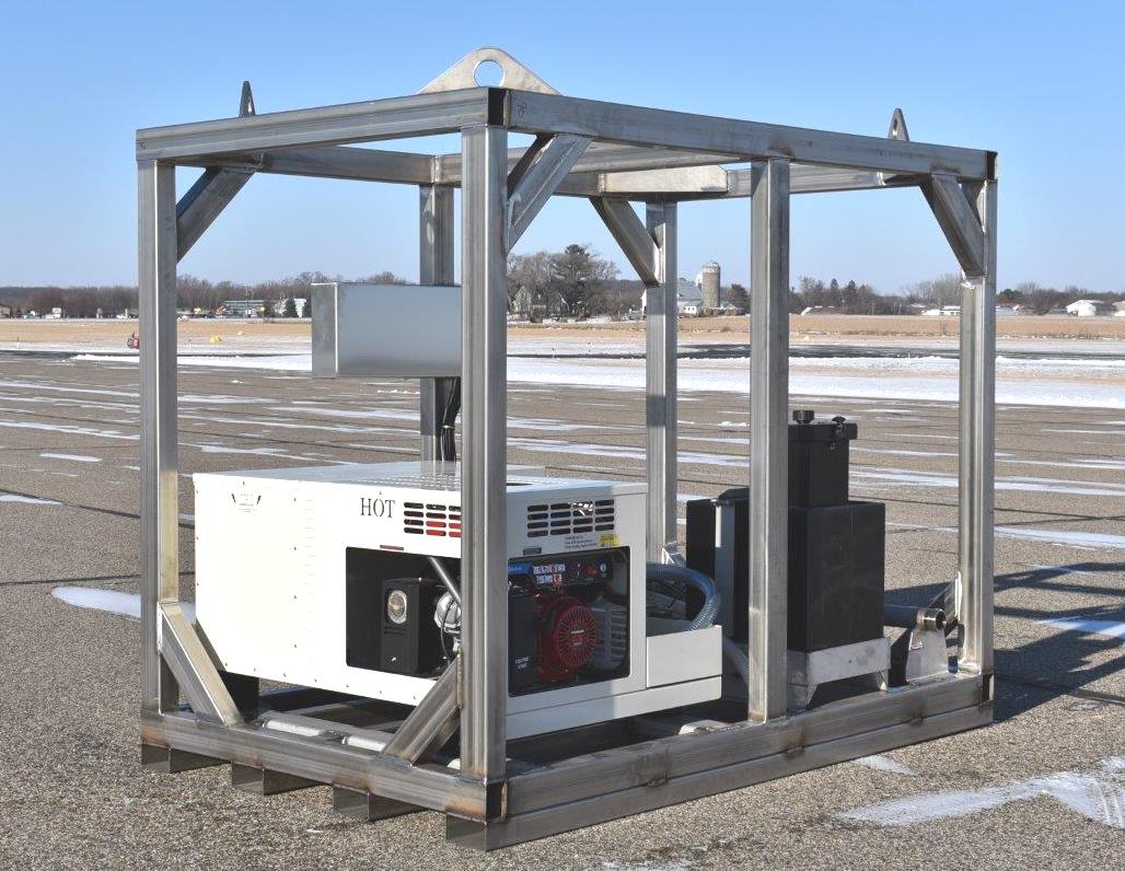


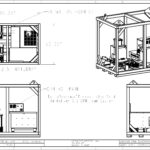
RatioResponse TurboFoam ENCAPSULATED SKID
Custom build for DOW Chemical
Bulletpoint Specs
Truck Type:
Chassis Model
- TUBULAR STAINLESS STEEL RATIORESPONSE SKID ENCOMPASSING FRAMEWORK
The entire skid unit framework, including transverse cross-members, longitudinal members, vertical riser tubes and horizontal perimeter railings shall be constructed of welded rectangular 2″ x 3″ stainless steel tubing and press-brake formed stainless steel structures. Stainless steel to have minimum wall thickness of .187″ for perimeter structures, .120″ minimum wall thickness for cross structures, and .187″ stainless steel fabrications. Tubular framework structure is to “fully encompass” all of the mounted components, offering surrounding protection, and “caged” structural integrity for the specified lifting eyes.Skid Unit framework assembly shall be wire-feed welded, with continuous welds at all butt-end and mitered joints, to completely seal all structures. Fabrications shall be provided, designed strategically to provide rigid underside support to top-side mounted accessories.
The framework shall consist of single piece full width and full length rectangular tubing’s, forming the outboard perimeter shape of the skid unit, with cross-tubing’s and longitudinal tubing’s at locations to be determined by the unit’s load capacity and mounting locations of exterior top platform mounted equipment and accessories.
Stainless steel mounting pads shall be provided for all equipment to be mounted to the lower portion of the skid unit framework.
Four (4) each, lifting plates shall be provided, with 3-inch through-the-hole eyes, located one (1) in each outboard corner of the skid frame. Lifting plates shall be fabricated of .5″ stainless steel, with bottom angular flange and welded cross-wise between perimeter frame, designed to allow choke-chain overhead lifting and to support the weight of the entire skid with a 2 to 1 safety factor
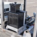
- ONBOARD 20-GALLON POLY CONCENTRATE RESERVOIR/TANK
One (1), 20 gallon capacity polypropylene thermoplastic concentrate reservoir is to be furnished, located onboard the RatioResponse TurboFoam encapsulated skid. The concentrate reservoir body and end bulkheads are to be constructed of minimum .5″ thick, polypropylene, nitrogen-welded inside and out, and tested. The reservoir is to have transverse and longitudinal minimum .375″ thick swash partitions, interlocked and welded to each other as well as to the walls of the tank.The concentrate reservoir is to be equipped with: exterior top fill tower with lift-up cover and locking latch assembly and interior screen, bottom foam liquid drain, means for venting of concentrate reservoir, and appropriate size concentrate liquid outlet for use with specified concentrate injection system.
LIFETIME WARRANTY
The concentrate reservoir itself is to be covered by a “Lifetime” Warranty, against cracks, corrosion, or other failures caused by the tanks design and normal use of the same. The warranty ios to be between the tank manufacturer, and the purchaser.
CONCENTRATE RESERVOIR CRADLE
The concentrate reservoir is toll rest on and fit into a stainless steel rubber lined cradle. All reservoir-to-cradle horizontal and vertical “mating” areas are to be lined with minimum 60 DURO rubber cushion material. The cradle is to be 304 stainless steel for total corrosion protection
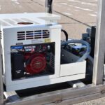
- 60-AMP CONTINUOUS DC VOLTAGE OUTPUT, GAS-ENGINE DRIVEN POWER UNIT
A BatesField Series 600 Honda Gas Engine-Driven DC Power Unit is to be provided, configured to, and provided with:
- Continuous 28Volts 60AMP Direct Current Output
- 24 Volt Battery Bank, connected to the TurboFoam 24VDC Motor
- Multi-Stranded High-Amperage Copper Battery Cables
- Hour Meter
- State of Charge Meter
- DC Voltmeter
- DC Ammeter
- Painted metal Enclosure
- 60-AMP CONTINUOUS DC VOLTAGE OUTPUT, GAS-ENGINE DRIVEN POWER UNIT
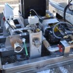
Fire Research TurboFoam model TFC362-025 direct injection Concentrate Proportioning system is to be provided. The system kit is to include a control module, a foam concentrate pump assembly with an electric motor, an electrical flush valve, a discharge flow sensor with mount for a 2.5″ pipe, check valves, foam concentrate and flush line strainers, cables, and instruction plates including operations, system diagram, and specifications.
The system is to provide the following capabilities:
Concentrate pump: 6.2 GPM
Maximum injection pressure: 400 PSI
A Concentrate Program B Concentrate Foam Program
Proportioning ratio: 0.1 to 1.0 % 0.5 to 10%
The microprocessor controlled system is to automatically maintain a selected foam percent mixture at the Waterway regardless of water flow fluctuations. It is to monitor the water flow through the Waterway and control the flow rate of concentrate from the Concentrate Tank. The pump is to inject concentrate under pressure into the Waterway to create the correct concentrate solution. Waeerway flow rate and concentrate percent are to be displayed. Total water and total concentrate flow is to be displayed with the push of a button.
The control module is to be panel mounted, waterproof, and have dimensions not to exceed 4 7/8″ high by 4 7/8″ wide by 2 1/4″ deep. The push button controls, digital discharge flow rate, foam percent, and message displays are to be located on the front of the control module. A USB port is to be accessed from the rear.
The foam pump assembly is to have an overall length less than 23 1/2″, width less than 10 1/4″, and a height less than 8 7/8″. The components of the assembly are to be mounted to a base and include a pump control box, a pump with an electric motor, a pressure relief valve, and a calibration bypass valve. The pump is to be a triplex plunger pump constructed of a die-cast body with cooling fins, a forged brass head, solid ceramic plungers, and viton seals. The pump is to have a custom electric washguard motor specifically designed for wet environments. The 1 hp pump motor shall operate at 24 volts DC and draw 50 amps.
Fire Research TurboFoam –FM1-2.5 discharge check valve assembly is to be installed, with a water way check valve, a check valve injector, and a drain.
Fire Research TurboFoam –EF0 electric flush valve and panel button are to be installed. The electric valve is to be controlled by the panel button and provide flush or prime capabilities for the foam concentrate pump.
The valve is have 1/2″ NPT fittings and be installed between the Waterway Pipe and a tee fitting on the concentrate tank to concentrate pump input line. The panel button is be an on/off switch with an indicator that mounts in a 1 3/8″ hole. It is have two wires for power and ground, and two wires that connect to the TFC control module.
- TURBOFOAM PROVIDED FEATURES
- Discharge Water Flow Display and a Foam Percent Display
- Menu Button to Access System Information and Data
- Two Line Alphanumeric Message Display
- Electric Flush Valve
- Programmable Control Module with USB Port Interface
- Electric Triplex Plunger Type Foam Concentrate Pump
- Check Valve Injector, Miscellaneous Check Valves and Strainers
- Discharge Paddlewheel Flow Sensor with Multiple Mounting Options
- Preset Button, Percent Increase/Decrease Buttons, and Digital Displays
- Automatic Proportioning Regardless of Discharge Water Flow Fluctuations
- Flow Totaling for Both Foam Concentrate and Discharge Water
- Remote On/Off Switch Option
- Tank Empty Warning
- Manual Mode
- CONTROL PANEL, TURBOFOAM WATERWAY INJECTION SYSTEM
A control panel is to be furnished, located on the tubular skid base encapsulated frame, facing outboard and easily accessible from ground level. The control panel is to be fabricated of brushed stainless steel, designed to accommodate the TurboFoam Digital Control Module, and optionally specified concentrate tank level indicator.
- OFFBOARD 1-1/2″ CONCENTRATE PICK-UP CONCENTRATE SELECTOR 3-WAY VALVE:
An Offboard 1-1/2″ Concentrate Inlet and Pickup Wand are to be furnished, piped to the Suction Inlet of the TurboFoam Concentrate Pump. Inlet Pickup is to be complete with 1-1/2″ Quick-Connectable Fitting, Hose with Mating Fitting, and Wand, configured to allow Concentrate to be drafted from a pail or barrel, directly into the Concentrate Pump.
PICK-UP CONCENTRATE CONNECTION
The external foam pick-up is to allow continued operation after the on-board concentrate tank is empty, or for the use of concentrate different than the concentrate in the onboard concentrate tank.
PANEL MOUNT VALVE AND QUICK-CONNECTION
A 1-1/2″ bronze 3-way valve is to be provided. The valve is to be panel mounted, plumbed to the Onboard Concentrate Tank, and an Offboard Quick-Connect Inlet Fitting. The 3-way valve is to function as the Concentrate Injection System’s Tank to Pump Valve in one position, and External Concentrate Pick-Up Suction Valve in the opposite position.
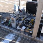
- 2-1/2 INCH CONCENTRATE PROPORTIONING SYSTEM WATERWAY
One (1) 2-1/2″ inside diameter waterway is to be provided, tig-weld fabricated of schedule-40 stainless steel pipe, equipped with the following accessories:
WATERWAY, FITTINGS AND ACCESSORIES
The waterway inlet is to be provided with a 2.5″ NST chrome plated brass rocker lug plug style Cap with chain, 2.5″ NST swivel female Inlet Adapter, specified Check Valve, 2-1/2″ i.d. schedule-40 stainless steel Waterway Pipe, insertion style Flow Meter Port, Concentrate Injection Port, 4-bolt Valve-Mating Flanges, specified Waterway Gate Valve, 2-1/2″ NST male Outlet Adapter, and a 2-1/2″ NST female Cap with chain.
INTAKE ONE-WAY CHECK VALVE
A 2-1/2″ bronze or stainless-steel one-way check valve is to be provided, upstream of the concentrate injection port (downstream of inlet adapter), designed to prevent back-flow of the pressurized concentrate into the Waterway feed source.
BALL GATE VALVE
An Akron model 8825, bronze 2-1/2″ ball style swing-out gate valve s to be provided, sandwich bolted between Waterway 4-bolt flanges. The valve is to include a swing-style manual lever actuator and handle.
FOAM/WATERWAY PIPING AND OUTLET
The waterway outlet shall be located on the curb (right) side, and shall include: 2.5″ NST chrome plated brass rocker lug hose cap with chain, 2.5″ NST male x 3″ TIPT rigid female chrome plated brass outlet adapter, 3″ i.d. schedule-40 3″ TIPT male threaded stainless steel weld nipple, 3″ i.d. schedule-40 30-degree stainless steel weld sweep elbow, a plugged .75″ stainless steel weld spud with .75″ brass 1/4-turn valve and plug (calibration port), 60″ of 3″ i.d. schedule-10 stainless waterway pipe, and a waterway 4-bolt Akron 8830 valve mounting weld flange.
FOAM SYSTEM ACCESSORY TAPS
Threaded, machined, and/or weld flange mounts are to be provided, permanently attached to the foam/waterway pipe, at the locations where required for use with the Proportioning System’s Injector and Flow Meter.